Products Description

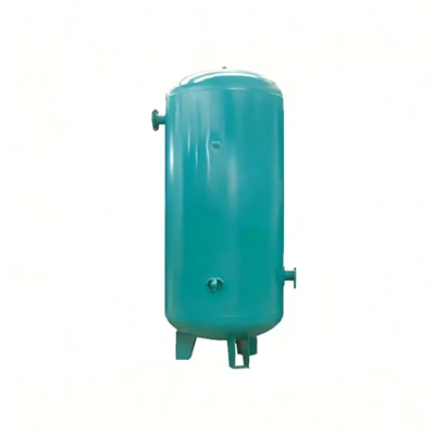
• Pressure-bearing structure standard: The oil-gas separator is a typical fixed pressure vessel. The cylinder body and the head are usually made of high-quality carbon steel (such as Q345R) through the automatic submerged arc welding process, and they must undergo strict non-destructive testing (radiographic or ultrasonic inspection) and hydraulic testing.
• Anti-static grounding process: When high-speed airflow passes through the glass fiber oil separation core, a large amount of static electricity is generated. If not promptly discharged, it may cause an explosion of oil and gas. Therefore, the upper and lower end covers and sealing gaskets of the oil separation core are embedded with conductive metal nails or metal nets, and they are connected to the tank body and the overall grounding system through flange bolts
• Built-in and external structure: Medium and large-sized screw machines mostly adopt the built-in process (the oil separation core is installed inside the barrel), featuring a compact structure and good sealing performance; Small units usually employ the external screw-mounted process (similar to the oil filter core directly screwed onto the valve seat), allowing for quick replacement without the need to remove the top end cover.
• Anti-emulsification and drainage design: The bottom of the tank is designed as an arc-shaped head, with a drainage port at the lowest point, facilitating the thorough discharge of the condensed water that precipitates after the machine is shut down and cooled, preventing the lubricating oil from emulsifying and deteriorating.

One rough separation (mechanical and centrifugal separation): After the high-temperature and high-pressure oil-gas mixture is discharged from the main unit, it usually enters the tank along the tangential direction of the barrel wall or passes through the baffle plate and then into the tank. Utilizing centrifugal force, gravitational sedimentation, and the sudden drop in speed caused by the impact of high-speed airflow on the barrel wall, approximately 85% to 90% of the large oil droplets are directly thrown onto the bottom of the tank.

Secondary fine separation (coalescence filtration): After the gas from the rough separation still contains micron-sized oil mist, it then passes from the outside to the inside through the precision oil separator on the upper part of the tank (mostly made of ultra-fine glass fiber material). The oil separator intercepts, undergoes inertial collision, and diffuses, causing the tiny oil mist to coalesce into large oil droplets and settle at the bottom of the filter core, ensuring that the oil content in the final output air is controlled within 1 to 3 ppm.
• Precise oil return pipeline: The lubricating oil that accumulates in the bottom groove of the oil separator core cannot drip by itself. In the process, a secondary oil return pipe will be inserted into the center of the oil separator core, directly reaching the bottom of the filter core.
• Pressure difference drainage: By utilizing the pressure difference between the interior of the oil and gas tank and the intake port of the main unit (or the low-pressure chamber), the pure lubricating oil accumulated at the bottom of the filter core is continuously drawn back to the main unit to prevent the oil from being carried away by the airflow again and causing "oil leakage".

The core components mainly perform the following three functions:
• Oil and gas separation: The high-temperature and high-pressure oil-gas mixture discharged from the main unit enters the tank. First, through the mechanical collision on the tank wall (coarse separation), most of the oil droplets fall to the bottom. Then, the mixed gas passes through the precision oil separation core on the upper part of the tank (fine separation), intercepting the extremely tiny oil mist, thereby obtaining clean compressed air.
• Storage of lubricating oil: The lower half of the tank (the area with wavy and diagonal shaded regions in the figure) is used to store the lubricating oil required for the system circulation.
• Establishment of system pressure: The internal pressure of the tank is the driving force that pushes the lubricating oil through the temperature control valve, cooler, and oil filter back to the main unit.
The main accessories connected around the tank body
• Oil observation mirror: Located at the bottom side of the tank, used to directly observe whether the lubricating oil level in the tank is within the normal range.
• Drain valve: Located at the bottom of the tank, used to regularly discharge the condensed water and impurities that have settled at the bottom after the machine is shut down and the pressure is released.
• Safety valve: Located at the top of the tank, automatically opening to relieve pressure when the pressure inside the tank exceeds the safety set value, preventing overpressure hazards.
• Pressure maintenance valve: Located at the top outlet, ensuring that a certain pressure (usually 0.4 - 0.45 MPa) is established in the tank when the machine is started, to ensure that the lubricating oil can circulate normally and supply oil.

Hot Tags: screw air compressor air oil separator, China screw air compressor air oil separator manufacturers, suppliers, factory, air compressor fuel tank, air compressor separator filter, air oil separator for screw compressor, diy vacuum pump from air compressor, portable compressed air tank, wheelbarrow air compressor replacement tanks